Newsletter

Where LLMs go wrong in firmware: a field guide to failure modes
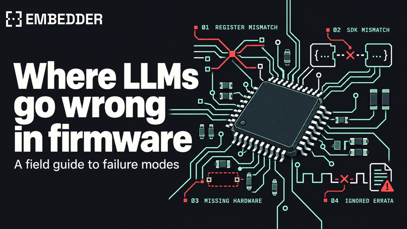
Invented register names, fabricated SDK calls, peripherals that aren't on the board, and ignored errata, each with a documented example.

The firmware builds with zero warnings and flashes without complaint. Then the board comes out of reset and stops at the first debug print. Halt the CPU and it is spinning in a tight loop, polling bit 7 of address 0x40004400 for a transmit-ready flag that will never be set.

This is what UART code written for an STM32F4 does on an STM32G0. Both parts put USART2 at the same base address. On the F4, offset 0x00 is the status register and bit 7 means the transmit register is empty. On the G0, offset 0x00 is control register 1, and bit 7 is an interrupt enable this code never set. A general-purpose model asked for a bare-metal G0 driver can produce the F4 layout with full confidence: that layout dates to the STM32F1 in 2007, and the one the G0 uses arrived with the STM32F0 in 2012.

A firmware failure mode, in this guide, is a repeatable way a large language model (LLM) writes code that reads as correct and is wrong for the exact part number, SDK release, board, or silicon revision it will run on. The four covered here are invented register names, fabricated SDK calls, peripherals that aren't on the board, and ignored errata. Each one comes from missing context, and the same models write correct firmware when they have it.

The underlying behavior has been measured outside firmware. A USENIX Security 2025 study generated 576,000 Python and JavaScript samples across 16 models and found that 19.7% of the packages those samples referenced did not exist, 205,474 unique invented names in total. An invented npm package fails at install, unless someone has already registered the name, which is the attack the study warns about. An invented register offset compiles, and the first sign of trouble is on the bench.

The four failure modes at a glance

Each failure mode traces back to a document the model did not have, and each is caught at a different stage.

Failure mode Example in this guide Where it gets caught Source that prevents it
Invented register names STM32F4 USART layout on an STM32G0 Compile time with vendor headers; on the bench with raw addresses Reference manual or SVD file for the exact part
Fabricated SDK calls gpio_pin_write() in a current Zephyr tree Compile or link time Headers and docs of the pinned SDK release
Peripherals that aren't on the board Clock setup that assumes a dev kit's crystal First boot Schematic and bill of materials
Ignored errata Register access straight after a clock enable on an STM32F405/407 On hardware, often only at higher optimization levels Errata sheet for the silicon revision

1. Invented register names

STM32 families reuse peripheral names and change the registers underneath them. On the F1 and F4, a USART has a status register (SR) and one data register (DR). On the F0, G0, L4, F7, and H7, status is read from ISR, flags are cleared through ICR, and data is split across RDR and TDR. The offsets changed along with the names.

Offset STM32F4 (RM0090) STM32G0 (RM0444)
0x00 SR CR1
0x04 DR CR2
0x08 BRR CR3
0x0C CR1 BRR
0x1C no register ISR
0x28 no register TDR

A model that defaults to the F4 layout on a G0 target writes something like this:

c
/* Target: STM32G071, bare metal, no vendor headers.
   Written with the STM32F4 USART layout. Clock and pin setup omitted. */
#define USART2_BASE   0x40004400UL
#define USART2_SR     (*(volatile uint32_t *)(USART2_BASE + 0x00))  /* F4 layout */
#define USART2_DR     (*(volatile uint32_t *)(USART2_BASE + 0x04))  /* F4 layout */
#define USART2_BRR    (*(volatile uint32_t *)(USART2_BASE + 0x08))  /* F4 layout */
#define USART2_CR1    (*(volatile uint32_t *)(USART2_BASE + 0x0C))  /* F4 layout */

void uart_init(void)
{
    USART2_BRR = 0x0683;                    /* on a G0 this lands in CR3 */
    USART2_CR1 = (1UL << 13) | (1UL << 3);  /* UE | TE on an F4; on a G0 this lands in BRR */
}

void uart_putc(char c)
{
    while (!(USART2_SR & (1UL << 7))) { }   /* on a G0 this polls CR1 bit 7 (TXEIE) */
    USART2_DR = (uint8_t)c;                 /* on a G0 this lands in CR2 */
}

With ST's CMSIS device header, this mistake is cheap. USART2->DR and USART2->SR do not exist in the G0's USART_TypeDef, so the build fails on those lines. Written against raw addresses, as above, the code compiles for either family. On the G0 the init function puts the baud rate value in CR3 and the control word in BRR, the peripheral is never enabled, and uart_putc() waits on a bit that stays at zero.

The same driver written for the G0, per RM0444:

c
/* Target: STM32G071, bare metal, register layout per RM0444.
   Clock and pin setup omitted. */
#define USART2_BASE   0x40004400UL
#define USART2_CR1    (*(volatile uint32_t *)(USART2_BASE + 0x00))
#define USART2_BRR    (*(volatile uint32_t *)(USART2_BASE + 0x0C))
#define USART2_ISR    (*(volatile uint32_t *)(USART2_BASE + 0x1C))
#define USART2_TDR    (*(volatile uint32_t *)(USART2_BASE + 0x28))

void uart_init(void)
{
    USART2_BRR = 0x0683;                    /* 9600 baud from a 16 MHz kernel clock */
    USART2_CR1 = (1UL << 3) | (1UL << 0);   /* TE | UE */
}

void uart_putc(char c)
{
    while (!(USART2_ISR & (1UL << 7))) { }  /* TXE / TXFNF */
    USART2_TDR = (uint8_t)c;
}

The check is mechanical: every address, register name, and bit position compared against the SVD file or reference manual for the exact part number. Embedder runs it through register lookup for the selected MCU, and can read the live value from the target to confirm what the code wrote.

2. Fabricated SDK calls

A fabricated SDK call is a function that does not exist in the SDK release the project builds against. Some existed in an earlier release. Others were assembled from the library's naming conventions and never existed anywhere.

Zephyr has an example of the first kind. gpio_pin_write() and gpio_pin_read() were deprecated in Zephyr 2.2, released in March 2020, and removed in Zephyr 2.4. Tutorials written before then are still online, and a model can reproduce their style in a project pinned to Zephyr 4.x:

c
/* Zephyr 2.1-era GPIO style. Removed APIs; does not build on current Zephyr. */
#include <zephyr.h>
#include <device.h>
#include <drivers/gpio.h>

void main(void)
{
    struct device *dev = device_get_binding("GPIO_0");

    gpio_pin_configure(dev, 13, GPIO_DIR_OUT);
    gpio_pin_write(dev, 13, 1);
}

In a current tree the old include paths, GPIO_DIR_OUT, and gpio_pin_write() are all gone, and the build stops. The current API takes the pin from devicetree:

c
/* Devicetree-based GPIO for current Zephyr (4.x). */
#include <zephyr/kernel.h>
#include <zephyr/drivers/gpio.h>

static const struct gpio_dt_spec led = GPIO_DT_SPEC_GET(DT_ALIAS(led0), gpios);

int main(void)
{
    if (!gpio_is_ready_dt(&led)) {
        return 0;
    }

    gpio_pin_configure_dt(&led, GPIO_OUTPUT_ACTIVE);
    gpio_pin_set_dt(&led, 1);
    return 0;
}

The second kind follows a library's naming pattern. STM32Cube's HAL has HAL_GPIO_WritePin() and its LL layer has LL_GPIO_SetOutputPin(). HAL_GPIO_SetPin() reads like a member of the same family and is in neither.

Both kinds fail at compile or link time, before anything is flashed. A harder case is a call that exists in two SDKs with different meanings. xTaskCreate() takes its stack depth in words in upstream FreeRTOS and in bytes in ESP-IDF, so a value copied between them is off by a factor of four on a 32-bit MCU and still builds. Our FreeRTOS-to-Zephyr migration guide covers that case and several like it.

The defense is to pin the SDK release before any code is generated, then give the model that release's headers and documentation. Embedder's FreeRTOS-to-Zephyr migrations with engineering teams start the same way: the destination release is pinned first.

3. Peripherals that aren't on the board

This failure has two levels. At the part level, the peripheral exists in the product family and is missing from your part number. At the board level, the chip has it and the board does not connect it, or connects it differently from the vendor's development kit.

The part-level version is caught by the compiler. ESP32 code that drives the on-chip DAC will not build for an ESP32-C3: ESP-IDF's DAC driver supports the ESP32 and ESP32-S2, and the C3 has no DAC to drive.

The board-level version compiles. The clock setup below is correct for an STM32F4 Discovery board, which has an 8 MHz crystal on the HSE pins:

c
/* Clock setup that assumes an 8 MHz crystal on HSE.
   Correct for an STM32F4 Discovery; wrong for a board with a
   different crystal, an external clock, or nothing on HSE. */
RCC_OscInitTypeDef osc = {0};

osc.OscillatorType = RCC_OSCILLATORTYPE_HSE;
osc.HSEState       = RCC_HSE_ON;
osc.PLL.PLLState   = RCC_PLL_ON;
osc.PLL.PLLSource  = RCC_PLLSOURCE_HSE;
osc.PLL.PLLM       = 8;                 /* 8 MHz / 8 = 1 MHz PLL input */
osc.PLL.PLLN       = 336;               /* 336 MHz VCO */
osc.PLL.PLLP       = RCC_PLLP_DIV2;     /* 168 MHz PLL output */
osc.PLL.PLLQ       = 7;                 /* 48 MHz for USB */

if (HAL_RCC_OscConfig(&osc) != HAL_OK) {
    Error_Handler();                    /* no clock on HSE: execution stops here */
}

ST's STM32F4 Nucleo-64 boards ship with that crystal position unpopulated. Current revisions feed an 8 MHz clock from the on-board ST-LINK into the MCU's oscillator input instead, which firmware selects with HSE bypass mode, not RCC_HSE_ON. A custom board may have a 25 MHz crystal, or nothing on HSE at all. With no clock source on HSE, the oscillator never reports ready, HAL_RCC_OscConfig() times out after 100 ms, and the CubeMX-generated Error_Handler() is an infinite loop, so the board appears dead before it prints a character. With a 25 MHz crystal, the same divider values put the PLL input at 3.125 MHz, outside its specified 1 to 2 MHz range, and the VCO far above its 432 MHz limit.

Bus addresses work the same way. A Bosch BME280 answers at I2C address 0x76 or 0x77 depending on how its SDO pin is strapped, and the schematic is where that is recorded.

The source for all of this is the schematic and bill of materials for the board revision on the bench. Embedder reads the design files from Altium, KiCad, Eagle, PADS, or Xpedition and checks firmware against the board's components, pins, nets, and power connections, so a clock source or an address strap comes from your netlist. Inferred addresses and part matches still get an engineer's review before a hardware change, and the documentation says so.

4. Ignored errata

A reference manual describes the chip as designed. An errata sheet lists where shipped silicon behaves differently, revision by revision. For the STM32F405/407 and F415/417, that document is ES0182, 45 pages at Rev 19 (July 2026).

Section 2.2.13 of ES0182, "Delay after an RCC peripheral clock enabling," says a peripheral's registers may not respond for a short time after its clock-enable bit is set: up to two AHB clock cycles for a peripheral on AHB, and up to 1 + the AHB/APB prescaler for a peripheral on APB. On an STM32F407 running at 168 MHz with APB1 at 42 MHz, a prescaler of 4, that is up to five cycles for USART2. This code follows the reference manual and skips the wait:

c
/* STM32F407 at 168 MHz, APB1 at 42 MHz (AHB/APB1 prescaler 4).
   Follows RM0090, ignores ES0182 section 2.2.13. */
RCC->APB1ENR |= RCC_APB1ENR_USART2EN;
USART2->BRR = 0x016D;                       /* 115200 baud from 42 MHz */
USART2->CR1 = USART_CR1_UE | USART_CR1_TE;

Compiled with GCC 12 through 14 at -O0, -O1, or -Os, a literal-pool load and a constant load sit between the clock-enable store and the BRR write. Two instructions is less than the five-NOP workaround the erratum gives for this prescaler, so that gap is slack, not a guarantee. At -O2 the compiler schedules the BRR store as the very next instruction after the clock enable, with no margin at all against the window the erratum describes. A dropped write leaves BRR at its reset value of zero, so the USART comes up enabled with no baud rate and nothing readable reaches the terminal. The same source can work at -O0 and fail at -O2, with no change to the driver.

c
/* STM32F407: with the ES0182 section 2.2.13 workaround. */
RCC->APB1ENR |= RCC_APB1ENR_USART2EN;
(void)RCC->APB1ENR;                         /* dummy read-back covers the enable delay */
USART2->BRR = 0x016D;
USART2->CR1 = USART_CR1_UE | USART_CR1_TE;

The erratum also allows a DSB instruction or a fixed number of NOPs in place of the read-back. ST's HAL already applies the read-back: its clock-enable macros read the enable register after setting the bit, under a comment with the erratum's title. A request for register-level code "without the HAL" drops the workaround along with the abstraction, unless the errata sheet is part of what the model reads.

The check here is the errata sheet for the silicon revision on the bill of materials, read against every peripheral the firmware uses. Embedder indexes errata alongside reference manuals, datasheets, and SVD files, and cites the section behind each hardware-specific value it writes.

The common cause: a document the model didn't have

Each failure is a missing fact, and each fact is written down somewhere outside the source tree: the reference manual for the exact part, the headers of the pinned SDK release, the schematic for the board revision, the errata sheet for the silicon revision. A model working from training data alone fills those gaps with the pattern it has seen most often, which tends to be an older part or a vendor's development kit.

The first control is to put the documents in front of the model and require a citation for every hardware-specific value. The second is to run the result on the target and keep the evidence, because code like the errata example reads correctly and fails on silicon.

A careful firmware engineer already makes these checks in review. Model-written drafts raise the volume of code that needs them. As a checklist:

  • Compare every register name, offset, and bit position with the SVD file or reference manual for the exact part number.
  • Pin the SDK release and resolve every API call against that release's headers.
  • Check pins, clock sources, bus addresses, and pull-ups against the schematic for the board revision.
  • Read the errata sheet for the silicon revision against every peripheral in use.
  • Build, flash, and observe on the target, and save the serial output, register dumps, and captures with the change.

Same models, better context

The models behind the four failures above are also the reason AI-written firmware is possible at all. An LLM with a domain-specific harness can read a reference manual of more than a thousand pages, follow a clock tree across chapters, write a driver in the project's own style, interpret a build log, and propose the next fix. Code generators and templates before them covered a small part of that range.

What a general-purpose model lacks is your project. It was trained to be good at everything from web apps to contracts, so it has no way to know which part number is on your board, which SDK release your tree is pinned to, or which silicon revision is on the bill of materials. Asked anyway, it answers with the most common pattern it has seen, and the four failures follow.

How Embedder checks code against the part, the board, and the silicon

Embedder is the layer that supplies both: the facts about your hardware and a way to test against it. It is an AI platform for firmware that runs on general-purpose models and gives them the datasheet, reference manual, SVD file, schematic, and errata for the exact part. It checks register values, bit fields, timing constants, and pin assignments against those sources, cites the source behind each hardware-specific decision, and flags values it cannot support for review.

Specialized agents share the work, and an orchestrator chains the build, flash, and test steps on the board through the compiler, debugger, probes, and instruments the team already uses, so the model sees what the chip did. Serial traces and register dumps are attached to its conclusions. The model does the reading, reasoning, and writing. Embedder supplies the facts and checks the result on hardware.

A general-purpose assistant can reach the same result if your team supplies the documents and builds the bench automation around it. Embedder packages that work for teams shipping production firmware: a catalog of hundreds of platforms and thousands of peripherals with their documentation, schematic ingestion, and hardware-in-the-loop testing in one workflow. Teams connect the model provider they choose, including local models, so each stronger model gets the same documents and the same bench loop.

Tell us where this breaks

This guide covers four failure modes with one main example each, and firmware has more. If a model-written driver passed your review and failed on your bench, send us the part number, the SDK release, and the symptom. If one of the examples above is wrong for a silicon revision or SDK release we didn't consider, we want that too. Errata sheets get revised, and this guide will be as well.

FAQ

What is an LLM failure mode in firmware?

It is a repeatable way a language model writes firmware that reads as correct and is wrong for the exact part number, SDK release, board, or silicon revision. The four covered here are invented register names, fabricated SDK calls, peripherals that aren't on the board, and ignored errata.

Why do LLMs get register names wrong?

Vendors reuse peripheral names across families while changing register names and offsets. STM32F4 USARTs use SR and DR. STM32G0 USARTs use ISR, RDR, and TDR at different offsets. Without the reference manual or SVD file for the exact part, a model falls back on the layout with the longest public history.

Does the compiler catch hallucinated firmware code?

Sometimes. Vendor headers turn a wrong register name or a removed SDK call into a build error. Raw addresses, board-level assumptions such as a missing crystal, and skipped errata workarounds all compile and then fail on hardware.

What is an errata sheet, and why does it affect AI-written firmware?

An errata sheet lists the ways shipped silicon differs from its reference manual, by revision. ST's ES0182 for the STM32F405/407 requires a delay after enabling a peripheral clock, and code written from the reference manual alone leaves it out.

Can a general-purpose AI model write production firmware?

It can contribute drafts when it is given the reference manual, SDK headers, schematic, and errata for the target, and when every change is verified on hardware. Without those inputs, the four failure modes in this guide are likely.

How does Embedder reduce these failures?

Embedder indexes manuals, datasheets, errata, and SVD files, reads schematics from Altium, KiCad, Eagle, PADS, and Xpedition, cites the source for each hardware-specific value, and runs build, flash, and test loops on the target board.

Is the LLM the problem?

No. The model is the part that reads the manual, reasons about the design, and writes the code. What a general-purpose model lacks is the project's part number, SDK release, schematic, and errata. Embedder supplies those, orchestrates the agents doing the work, and verifies the output on hardware.
The Next Battleground for Silicon Vendors Is Developer Experience

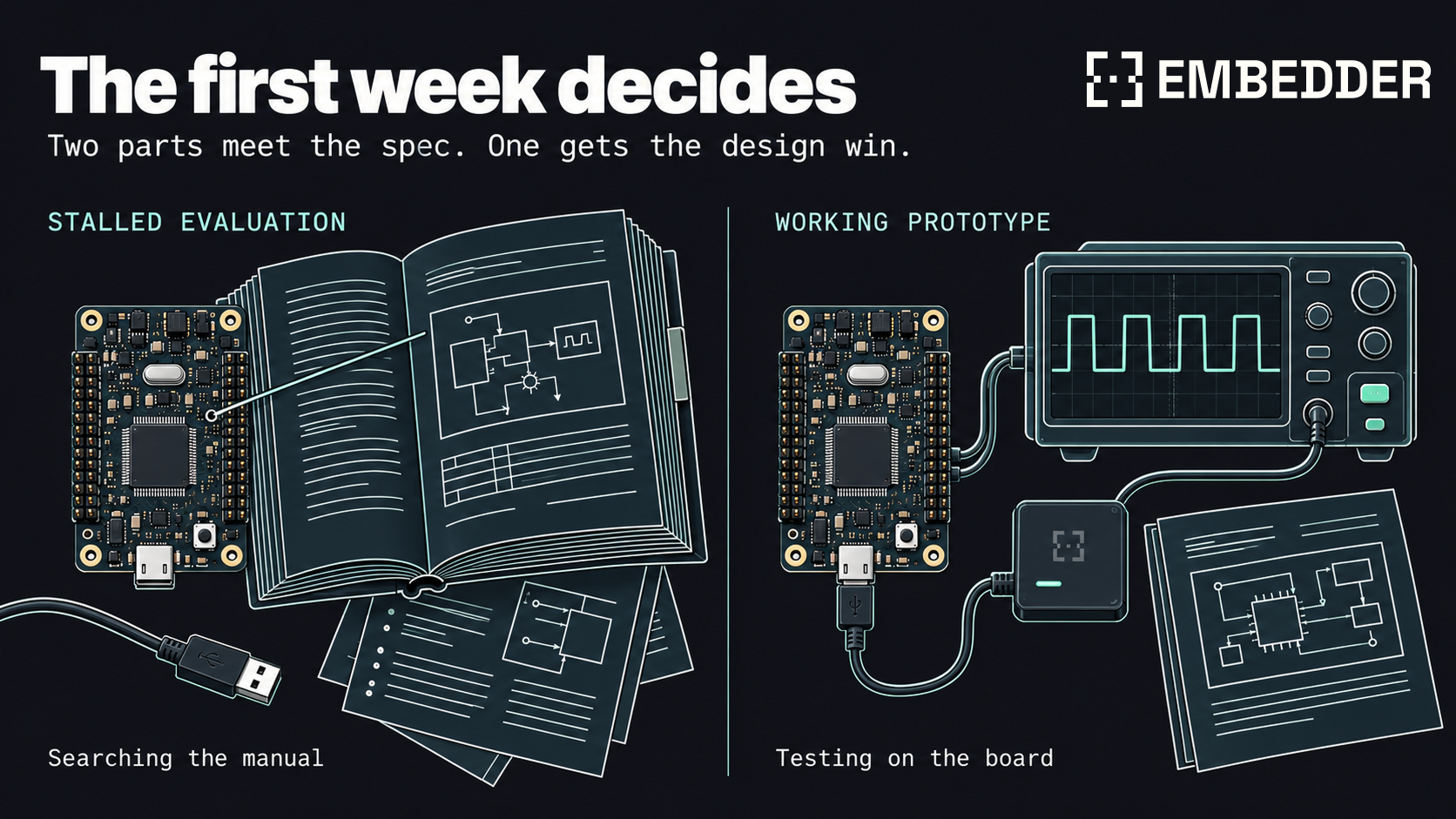
Two evaluation kits land on a firmware engineer's desk in the same week, both meeting the spec at about the same price. By Thursday one has a working sensor driver and a passing test on the board, and the other is still blinking an LED while someone digs through a 1,500-page reference manual for one clock setting. The second chip might be the better part, but it won't get the design win.

For decades, silicon vendors competed on performance, power, and price. Everything between unboxing a chip and running verified firmware on it (documentation, SDKs, drivers, board support packages, reference designs, debug tooling, support) counted as table stakes. That ordering made sense when every engineer ramped on a new part at roughly the same human speed.

Developer experience used to break ties between chips on the shortlist. Now it decides which chips stay on the shortlist long enough to be considered, and the reason is simple: agents.

In JetBrains' Developer Ecosystem Survey 2026, 90% of professional developers used AI coding agents at work at least weekly, and 68% used them daily. An engineer who closes tickets with an agent all morning expects that pace when bringing up a new chip in the afternoon. Hours spent clicking through a GUI configurator or searching a reference manual become part of how they judge the chip.

Trust hasn't kept up. In Sonar's 2026 State of Code survey, 96% of developers said they don't fully trust AI-generated code to be functionally correct. Firmware makes that gap especially expensive: a plausible answer can compile cleanly and still be wrong on the board. Engineers want faster answers, but they also need evidence.

A vendor that provides both benefits twice. Its own engineers can ship SDKs, drivers, and reference designs faster, and its customers can reach a working prototype sooner. Both shorten the path to a design win.

Compiling is not evidence

A wrong register value can compile, link, and flash without complaint. The failure might show up immediately on the bench, or six months later in the field. The compiler checks the code against the language. It can't tell an engineer whether bit 4 of a clock control register should be set on this silicon revision.

So an engineer evaluating a new part asks an agent for a driver, then asks where each value came from. Without the relevant documentation, there's no reliable way to distinguish a documented setting from a plausible guess.

That creates two requirements. Provenance tells the engineer where a decision came from: a register description, a table, a page. Verification tells them whether it behaves correctly on their board: a register dump, a scope capture, a current trace.

Neither is enough alone. A citation can point to a mistake in the datasheet. A bench test can pass because the code relies on an undocumented quirk. An agent doing firmware work needs to show the source behind its decisions and the measurements supporting its results.

What vendors have shipped, and where it stops

Several large MCU vendors now provide tools that connect AI agents to their documentation and development environments, often through the Model Context Protocol, or MCP:

  • Nordic Semiconductor's MCP servers expose nRF Connect SDK documentation, API references, device configurations, and field data from nRF Cloud. They work with Claude Code, Cursor, GitHub Copilot, and other assistants.
  • Texas Instruments ships MCP servers inside Code Composer Studio for building projects, running the debugger, using SysConfig, and reading serial output.
  • Microchip's MPLAB AI Coding Assistant for VS Code has an agent mode and MCP tools for documentation, example projects, and supported evaluation boards.
  • Analog Devices' AI Debug Assistant, in preview in CodeFusion Studio, connects MCP-compatible agents to live debug sessions for hardware inspection and fault diagnosis.
  • Renesas made Renesas 365, powered by Altium, generally available in March 2026. The cloud platform connects device selection, system design, and lifecycle management, with AI guidance built in.

Developers are also filling gaps themselves. Open-source tools for STM32 include GDB-based debugging on real hardware, with flashing and register inspection.

These tools vary in how much of the work an agent can do. Reading documentation helps it propose an answer. Access to configuration and build tools lets it implement that answer. Debugger access lets it inspect what happened when the code ran. TI and ADI have reached that last step, which gives an agent a way to check its work against the target.

The customer's board adds another requirement. A car door module might combine one vendor's Bluetooth SoC, another's microcontroller, and a third's power management IC. Bringing it up means working across all three, against the customer's schematic and with the probes and instruments on their bench.

Vendor tools are generally centered on their own ecosystems, though some, including Renesas 365, support mixed-vendor systems. Their usefulness still depends on how well they fit into a setup the vendor doesn't control. An engineer needs the agent to work with the repository, toolchain, and board already in front of them.

Firmware can hold up new silicon

Every chip ships with a software product attached, whether or not anyone prices it separately. Before a customer starts building, the vendor's engineers have written peripheral drivers, hardware abstraction layers, board support packages, RTOS ports, example projects, and evaluation kit firmware. Each new variant and toolchain adds implementation and maintenance work.

Software support can lag the silicon, especially for new variants and less common peripherals. The part may be ready while a driver is incomplete, an RTOS port is missing, or the only example targets a different board. If AI shortens chip design cycles, SDK teams will have even less time to close those gaps.

Agents can take on much of the first implementation and test work. Inside an established vendor's repository, the process can look like this:

  1. Read the reference manual, including register maps, the clock tree, and errata.
  2. Draft an implementation plan that cites the source behind each hardware-specific decision. An engineer reviews and corrects it before implementation.
  3. Write the drivers and board support using the vendor's existing build system and conventions.
  4. Build, flash, and test on the target through debug probes and bench instruments.
  5. Attach serial logs, register dumps, and signal captures to the results so an engineer can assess them.

Engineers still decide what gets built, whether the approach is right, and whether the result is ready to ship. They spend less time producing the first implementation and more time reviewing it, improving the architecture, and covering parts that have waited for software support.

Zephyr is a useful example. Supporting a part requires devicetree descriptions, Kconfig, drivers, build integration, and runtime validation on hardware. Much of that work also appears when a customer migrates from FreeRTOS to Zephyr. Better vendor support reduces the work customers have to repeat.

Cheaper switching weakens software lock-in

For many customers, the difficult stretch runs from the evaluation kit to their own board. The dev kit example works. Then they change the pins, add a sensor, or use a different power topology, and the example no longer describes the hardware they need to ship.

Agents can shorten that stretch. Embedder, for example, reads the schematic alongside the datasheet to work out pin muxing, pull-ups, bus addresses, and relevant errata. It works in the customer's existing repository with their compiler, build system, debugger, and RTOS, across hardware from multiple manufacturers.

Migration creates a similar problem. A customer may want the security, networking, or performance of a vendor's next-generation part, but moving the legacy firmware takes time they haven't budgeted. An agent with access to both parts' documentation and the new board can help port the HAL, peripheral code, and RTOS integration.

For the vendor, an easier migration gives the customer a reason to stay for another generation. A difficult one gives them a reason to evaluate alternatives.

The same tools make those alternatives easier to adopt. In the Linux Foundation's Zephyr Turns 10 report, 49% of respondents cited easier hardware portability as one of the biggest impacts of adopting Zephyr. Agents can reduce the remaining work of adapting firmware to another part.

Switching costs have helped vendors retain customers for years. Engineers stay with a family because they know its SDK, configurator, and quirks. As ports become cheaper, that familiarity carries less weight.

We think vendors should respond by making their parts easier to move to. The product engineers judge is the silicon together with the experience of using it. A familiar SDK will offer less protection for a part that takes longer to bring up or performs worse once it runs.

FAEs hold what the datasheet can't

Field application engineers, or FAEs, bring a vendor's knowledge to the customer's bench. They're often among its most experienced engineers, and there are far fewer of them than there are customers. Their time gets allocated accordingly. Large accounts get a named FAE. Smaller teams rely on distributors, forums, and support queues.

Many questions reaching an FAE already have answers in the documentation: a clock that won't lock, a pin mux conflict, a driver returning zeros, an erratum the customer missed. Answering them takes time away from design reviews and problems that require experience with the part.

An agent grounded in the vendor's documentation can handle those questions where they arise, with the relevant section cited. When a problem needs an FAE, it can arrive with the investigation already recorded: serial traces, register dumps, schematic context, and the hypotheses tested on the board. The FAE can use the same tools to reproduce it.

Michael Polanyi's observation that we know more than we can tell applies well here. An agent can use what's written down and what it can measure. An FAE may know which reference design worked in a similar product, which trade-off will cause trouble in production, or when the datasheet is wrong.

That experience is difficult to put into documentation. Handling routine questions with agents gives FAEs more time for the design decisions where it matters.

Evaluations end without anyone deciding to end them

A stalled evaluation can disappear quietly. An engineer stuck for a week may never file a ticket. They switch to another part, and the vendor learns about it months later when the opportunity fails to close.

Losing an evaluation can mean losing years of orders. In the Linux Foundation's Zephyr Turns 10 report, 52% of organizations reported supporting Zephyr-based embedded products for five to ten years or longer. Firmware from one product often becomes the starting point for the next, so an early design win can carry into later designs.

Small teams have little room for a slow bring-up. They may have no named FAE, no slack in the schedule, and a competing evaluation kit that already works. Individually, those teams place small orders. Together, they represent more customers than an FAE team can support by hand, and some grow into larger accounts.

An agent that helps them reach working hardware gives the part a chance to be evaluated on its performance. It also extends useful support to teams the vendor's engineers may never meet.

Vendors should track the time from kit arrival to the first verified peripheral on the customer's own board, by part and customer segment. It gives them an earlier view of bring-up problems than a sales opportunity that goes quiet months later.

Agents could change what vendors build

The immediate opportunity is to make existing chips easier to use. A longer-term possibility is that agents change which hardware vendors can reasonably expect customers to program.

Abstractions hide some of what makes a chip different

A modern automotive or industrial controller has several layers between the application and the hardware: drivers, HALs, configuration tools, and frameworks such as AUTOSAR. Those layers let teams reuse code, integrate components, and maintain systems without programming every device from scratch.

They also limit which hardware features an application can reach easily. A cross-vendor driver API exposes what different parts have in common. A vendor HAL exposes the features its SDK team has implemented. A configuration tool exposes the settings someone added to its interface.

This matters in microcontrollers, where many vendors license the same Arm Cortex-M cores. Much of the difference between parts lies in the peripherals: timers, DMA engines, analog front ends, and crypto blocks. A common interface may leave some of those differences out.

An agent that reads the reference manual and tests on the board could make more of them practical to use. It could configure a DMA chain or a timer's capture modes directly from the register description, then measure whether the result meets the application's requirements.

Teams would still need stable interfaces and maintainable code. Certification would still favor known, reviewed components. But writing and maintaining a part-specific implementation could become cheaper, including when the hardware changes.

That makes documentation and tooling part of whether a feature gets used. A precisely documented peripheral with scriptable tools is easier for an agent to target and test. One described only in a scanned PDF, or missing from the SDK, may remain unused even when it would improve the application.

Designing for the application

Hardware architects already face this constraint. Specialized blocks can improve throughput, power consumption, or timing, but customers need a workable way to use them. A controller might offload network security, packet handling, motor timing, or signal processing. It might divide work among different kinds of cores.

The programming effort grows with the combinations. Which tasks should share a bus? What happens to latency when two accelerators use the same memory? Which core should handle an interrupt when battery life matters more than response time?

The answers depend on the application and may change as the firmware changes. Teams can spend considerable time managing those interactions, or settle for a simpler design that leaves some hardware idle.

An agent could help explore those assignments. Given a workload and a goal, it could propose how to divide tasks among cores and accelerators, run the application, and compare the result against timing captures, current measurements, and trace data. It could repeat that work when the application changes.

If that proves reliable, architects would have more freedom to build specialized hardware without requiring customers to manage every interaction by hand. Vendors would have another way to retain customers: hardware that delivers a measurable advantage and tools that make it accessible.

Start with chips that already ship

Customers already have a smaller version of this problem. Security features go unconfigured. Low-power modes go unused because entering and leaving them correctly takes too much work. Peripherals that could offload the CPU sit idle while the main core runs the operation in a loop.

Agents can help investigate those features on parts customers already own. For a vendor, making better use of existing silicon is a practical place to start, with results that customers can measure before choosing their next part.

The broader architectural argument remains a hypothesis. It depends on agents doing this work reliably enough that engineers can maintain and trust the resulting firmware.

Where this argument breaks down

We expect developer experience to influence more design wins over the next few years. It still has limits.

Documentation can be wrong, and bench tests cover only the conditions tested. An agent can collect evidence faster without settling every question about behavior in production.

Physical validation also takes time. Writing more firmware doesn't eliminate test setup, environmental testing, or the need to investigate intermittent failures.

Experienced engineers remain necessary for undocumented behavior, analog problems, and design decisions that depend on the product's requirements. Safety-critical firmware still requires human review and traceability, regardless of who wrote the first draft.

And price, supply, and long-term availability still decide plenty of designs. No SDK fixes a part you can't buy.

If you build chips, tell us what we got wrong. Bring the part your FAEs get the most tickets about to a working session with our team, and we'll see what an agent can do with it on the bench.

If you write firmware, tell us about your setup: which chips came up quickly with an agent, and which ones you gave up on.

Frequently asked questions

Why is developer experience becoming more important for silicon vendors?

Engineers who use agents in their daily work expect them to help with a new chip too. Documentation the agent can read, tools it can operate, and tests it can run on hardware all affect how quickly a team reaches a working prototype. That can determine whether a part stays under evaluation.

How can AI help a vendor's SDK team?

An agent can draft drivers, board support, and RTOS ports using the part's documentation, then build and test them on the target. Engineers review the implementation and its evidence, giving them more time for architecture and gaps in software coverage.

Does AI replace field application engineers?

Agents can answer documented questions and gather evidence before an escalation. FAEs still handle the work that depends on experience with the part and the customer's design, including problems the documentation doesn't explain.

Why do customers abandon chip evaluations?

Bring-up can consume more time than a team has available. When another part already works on the bench, the team may move on without raising a support ticket. Better documentation, tools, and early help give the original part more time to be judged on its performance.

What makes silicon agent-ready?

Documentation that can be searched and cited, precise hardware descriptions, scriptable configuration and build tools, and access to debugging and hardware tests. Engineers also need examples that work on the supported target and a clear record of what was tested.

How could AI change chip architecture?

Agents could make specialized peripherals and heterogeneous cores easier to use by helping assign work, implement it, and measure the result on the board. If that process becomes reliable, architects could offer hardware features that would otherwise demand too much programming effort.

What hardware and firmware does Embedder support?

Embedder works across MCU and board platforms from multiple manufacturers. It supports C, C++, and Rust in bare-metal and RTOS projects, including FreeRTOS and Zephyr, and teams can add custom hardware with its documentation.

Migrate from FreeRTOS to Zephyr with AI

Moving from FreeRTOS to Zephyr changes how firmware describes hardware, schedules work, manages dependencies, and interacts with drivers. AI can help investigate the existing application, propose changes, and repeat build and test steps. The engineering work is deciding which behavior must survive the migration and collecting evidence that it does.

You can do this with a general-purpose AI coding assistant connected to your repository and development tools. A firmware-focused option such as Embedder may make the process easier by bringing hardware documentation, debugging, and measurements into the same workflow. Either approach needs a reproducible environment, explicit requirements, and tests on the target hardware.

Watch video · Watch on YouTube ↗

Understand what the migration should accomplish

Start with a product requirement: support a new board, consolidate middleware, add connectivity, or reduce the cost of maintaining several hardware variants. If the existing FreeRTOS application meets its requirements and has well-supported drivers, retaining it may be the better engineering decision.

Published migrations illustrate different reasons to make the change. Boston Engineering moved an STM32 application to Zephyr for CANopen integration and future connectivity. During the port, the team replaced custom SPI flash code and an untested ringbuffer with Zephyr facilities, but also encountered an ISR-related pipe bug that required an upstream fix. Reusing a subsystem can reduce maintenance while still introducing behavior that needs testing. See Boston Engineering’s migration account.

Atym’s Ocre runtime had a broader platform requirement: consistent hardware interfaces and fewer independently managed libraries and middleware components. Its account also describes variation in driver and board-support quality. That makes support for the exact peripheral features you use an early investigation, even when the board already appears in Zephyr’s catalog. See Atym’s FreeRTOS-to-Zephyr migration.

Define the first milestone narrowly: the current application’s essential behavior running on Zephyr. Record optional changes—such as adopting a new bootloader or replacing an application messaging framework—as separate decisions with their own tests.

1. Map the application and record a baseline

Ask the AI assistant to trace RTOS dependencies through application code, wrappers, interrupt handlers, middleware, and build variants. A list of xTaskCreate() calls is only a starting point. The useful output explains how work moves through the system and which assumptions connect the components.

For each task, record priority, stack allocation, activation source, deadlines, shared resources, and shutdown behavior. For each communication path, record whether it carries copied data, pointers, event bits, or counts. Include queue capacity, buffer ownership, timeout behavior, and what happens when the consumer falls behind.

Jacob Beningo’s migration guide recommends analyzing the architecture before porting primitives and considering an OS abstraction layer. A small abstraction can let you test FreeRTOS and Zephyr implementations against the same application contract. Its value depends on whether you need both implementations long term. If the application already uses CMSIS-RTOS v2, review Zephyr’s documented compatibility limitations before assuming the port will be transparent.

Capture the source SDK, FreeRTOS version, compiler, board revision, build options, and firmware artifact. Run representative workloads and save measurements with their method and tolerances.

Area Baseline to capture
Timing Sampling period, jitter, interrupt-to-thread latency, deadline misses
Data flow Throughput, ordering, queue occupancy, dropped or overwritten messages
Memory Flash and RAM usage, task stacks, heap behavior under sustained load
Hardware Bus settings, transaction traces, peripheral error and recovery behavior
Power Sleep current, wake latency, energy over a representative duty cycle
Persistent state Calibration, credentials, settings, and behavior after interrupted writes

A useful planning request is specific about both evidence and constraints:

text
Plan a FreeRTOS-to-Zephyr migration for the current board. Inventory RTOS
dependencies, including wrappers, middleware, and ISR interactions. Cite
the files and functions supporting each finding, and flag unknowns.

Preserve the sensor API, 10 ms sampling period, sample ordering, and UART
packet format. Use the recorded baseline for timing and memory limits.
Check board and driver support in the selected Zephyr release. Propose
incremental changes and tests before editing. Identify any assumption
that requires a schematic, datasheet, or measurement to confirm.

The example’s 10 ms period is a requirement to replace with your own, not a default for the migration.

2. Establish a reproducible Zephyr build

Choose the destination release before generating code. Give the assistant that release’s headers, bindings, examples, and documentation. Vendor SDKs can carry different driver implementations and configuration options from upstream Zephyr; mixing examples across versions can produce plausible code that does not build.

Create the smallest application that boots and produces observable output. Establish its CMakeLists.txt, prj.conf, board target, and required overlays before moving application services. Zephyr’s application development guide explains this structure.

Once the toolchain and workspace are configured, a basic sequence is:

sh
# Replace YOUR_BOARD_TARGET with the target for the selected SDK release.
west build -p always -b YOUR_BOARD_TARGET -d build/zephyr-port path/to/app
west flash -d build/zephyr-port

The board’s supported runner and probe setup determine how flashing works. A pristine build helps eliminate stale configuration when changing boards or overlays. See Zephyr’s build, flash, and debug commands.

Record dependency revisions as well as the application commit:

sh
west manifest --freeze -o west-frozen.yml

The frozen manifest records project revisions as commit SHAs. Preserve local patches, the manifest repository’s revision, toolchain versions, and build commands separately. Together, these let another engineer reproduce the result.

Ask the assistant to explain each build failure against the selected source tree. A missing driver, an unmet Kconfig dependency, and an obsolete API call require different fixes.

3. Bring up hardware one peripheral at a time

Zephyr divides configuration between devicetree, Kconfig, and runtime APIs. Devicetree describes hardware and its boot-time configuration. Kconfig selects software features and drivers. Some settings can still change at runtime. See devicetree versus Kconfig.

For a sensor on an I2C bus, trace the bus controller, pinctrl configuration, device address, bus frequency, interrupt pin, power supply, and driver binding. Give the AI assistant the schematic and existing initialization code, then ask it to justify each proposed setting against those sources. Do not let a development-board example silently determine the custom board’s wiring.

Inspect the generated configuration after building. In a typical single-image build, build/zephyr-port/zephyr/zephyr.dts shows the resolved hardware description and build/zephyr-port/zephyr/.config shows the selected software configuration. An undefined reference to __device_dts_ord_<N> error commonly means a referenced device has no allocated driver instance; check whether the node and its driver are enabled. Zephyr’s devicetree troubleshooting guide walks through that diagnosis.

Remember that prj.conf requests settings; .config contains the resolved result. An assignment can be ignored when its dependencies are unmet. Ask the assistant to trace those dependencies instead of repeatedly adding the same flag. See Kconfig configuration values.

For each peripheral, verify the features the application actually needs: DMA, asynchronous transfers, chip-select behavior, interrupt mode, sleep states, and error recovery. If retaining vendor HAL code, assign ownership explicitly so it does not compete with a Zephyr driver for the same peripheral, interrupt, DMA channel, or clocks.

NXP’s Platform Accelerator port shows the potential benefit of completing this work: its team replaced board-specific integration code with common code using Zephyr’s driver interfaces, with board configuration handling differences such as display support and heap size. That portability depended on the required hardware and runtime support being present. See NXP’s porting presentation.

Make the first hardware milestone concrete: one valid sensor transaction reaching the output. Add periodic acquisition, buffering, and concurrent activity afterward.

4. Port kernel behavior explicitly

For each conversion, ask the assistant to document the old behavior, the proposed implementation, and a test that would expose a mismatch. Several differences deserve particular attention.

Priorities, stacks, and startup order

FreeRTOS assigns higher task priority to larger numbers. Zephyr assigns higher thread priority to smaller numbers: 0 is the highest preemptible priority, while negative values select cooperative priorities. Preserve the intended ordering while accounting for system threads and time slicing. An arithmetic conversion that produces negative priorities can change the scheduling model. See FreeRTOS scheduling and Zephyr threads.

Upstream FreeRTOS specifies xTaskCreate() stack depth in StackType_t elements. With four-byte elements, a depth of 512 represents 2,048 bytes. Zephyr’s K_THREAD_DEFINE() takes a size in bytes. Check the source SDK: ESP-IDF already uses bytes for task stack sizes. This conversion gives a starting allocation; different call paths and libraries can change actual stack demand. See the FreeRTOS API, Zephyr thread API, and ESP-IDF documentation.

Initialization order also changes. Zephyr is already scheduling when application main() runs; a FreeRTOS sequence that creates objects and then calls vTaskStartScheduler() cannot be copied unchanged. AMD’s producer/consumer example creates Zephyr threads with K_FOREVER as their initial delay, initializes shared objects, then calls k_thread_start(). The example also distinguishes allocating thread storage from initializing a thread at runtime. See AMD’s FreeRTOS-to-Zephyr porting example.

Queues, ownership, and interrupt context

A fixed-size FreeRTOS queue often maps to k_msgq, which copies each message. If the message contains a pointer, only the pointer is copied; the referenced buffer still needs an ownership and lifetime rule. Pointer-based queues and FIFOs have different requirements and should be evaluated separately. See Zephyr message queues.

For an already available sample, a minimal enqueue helper could look like this:

c
#include <stdint.h>
#include <zephyr/kernel.h>
#include <zephyr/sys/atomic.h>

struct sample {
    uint32_t sequence;
    int32_t value;
};

K_MSGQ_DEFINE(samples, sizeof(struct sample), 16, 4);
static atomic_t dropped_samples;

/* Called from a regular ISR after the sample is available. */
void enqueue_sample_from_isr(uint32_t sequence, int32_t value)
{
    const struct sample sample = {
        .sequence = sequence,
        .value = value,
    };

    if (k_msgq_put(&samples, &sample, K_NO_WAIT) != 0) {
        atomic_inc(&dropped_samples);
    }
}

This illustrative fragment implements an explicit drop-newest policy and records unsuccessful submissions. A consumer and the hardware-specific interrupt handler are still required. Test whether dropping is acceptable, whether capacity is sufficient, and whether the consumer can sustain the input rate. For lossless acquisition, use an appropriate buffering or flow-control design and verify it under overload.

Review return-value tests during conversion: k_msgq_put() returns zero on success, unlike FreeRTOS queue-send checks against pdPASS. In ISR context, use a nonblocking timeout. See the message queue API.

The fragment is unsuitable for a zero-latency interrupt: Zephyr defines kernel API use from that context as undefined behavior. Removing a FreeRTOS FromISR suffix is therefore insufficient; verify every operation’s permitted context against Zephyr’s interrupt rules.

Notifications, event flags, and locking

FreeRTOS task notifications can represent a wakeup, a count, event bits, or a value with overwrite semantics. Choose the replacement from the producer and consumer behavior. A binary semaphore can represent “work is available,” but it cannot preserve an arbitrary number of pending occurrences. A counting semaphore retains counts within its limit; a queue retains individual payloads. See FreeRTOS task notifications.

Event flags need special care. In k_event_wait(), reset=true clears existing events before waiting. It does not mean FreeRTOS-style clear-on-exit. Zephyr 4.3 provides k_event_wait_safe() for atomic consumption of received bits; verify availability in the pinned SDK and check multi-waiter behavior. Also distinguish k_event_post(), which merges event bits, from k_event_set(), which replaces the current set. Test events posted before the wait, concurrent posts, wait-any versus wait-all, and multiple consumers. See Zephyr’s event API.

Keep mutex ownership distinct from semaphore signaling. Zephyr mutexes support recursive locking and priority inheritance but are not intended for ISR use. Check lock ordering and timeout paths, especially where a task holds one lock while waiting for another. See Zephyr mutexes.

If moving to multiple cores, review critical sections separately. Preventing scheduling on one CPU does not establish mutual exclusion against another CPU. Choose the appropriate Zephyr lock or atomic operation for the shared state, and keep spinlock-protected sections bounded and nonblocking. See Zephyr’s SMP guidance.

Timers, deferred work, and periodic execution

FreeRTOS software timer callbacks execute in the timer service task and must not block. Zephyr k_timer expiry callbacks execute in interrupt context. A callback that accesses a driver or performs substantial processing may need to signal a thread or submit work, with the added scheduling delay included in its timing budget. See FreeRTOS software timers and Zephyr timers.

A work item is not an event counter. Submitting a k_work item that is already queued does not add another copy, and a busy shared workqueue can delay its execution. Keep individual samples in a queue or buffer when every occurrence matters. A dedicated workqueue can isolate workloads, but adds a thread and stack that must be budgeted. See Zephyr workqueues.

Review periodic loops independently. Processing a sample and then sleeping for 10 ms produces a period longer than 10 ms. When the source uses a delay-until schedule, preserve its reference timeline and define the overrun policy: catch up, skip missed periods, or report a fault. Zephyr supports absolute timeouts, but clock resolution and scheduling latency still affect execution. See Zephyr’s timing documentation.

5. Include the rest of the product

A working sensor loop leaves several migration boundaries to check:

  • Networking and Bluetooth. Inventory connection-state callbacks, buffer ownership, retry behavior, and persistent identities or bonds. Test reconnects, interrupted transfers, and operation under concurrent radio traffic. Treat a vendor-stack replacement as its own integration effort.
  • Stored data. Preserve flash partitions, calibration, credentials, and settings formats deliberately. Zephyr’s settings subsystem supports multiple storage backends, which does not establish compatibility with the source firmware’s bytes. As a concrete example, enabling CONFIG_NVS_DATA_CRC on existing NVS data written without that option invalidates that data. Plan conversion and interrupted-conversion tests. See settings and NVS.
  • Boot and updates. If introducing MCUboot, review image layout, signing, confirmation, and recovery alongside the installed bootloader. Test an upgrade from an actual source-firmware device, including its stored state. Booting a freshly erased board exercises a different path. See MCUboot’s design.
  • Power and recovery. Check peripheral suspend/resume, wake sources, watchdog feeding, and behavior after a timeout. A sleeping application thread does not establish that every device has entered a low-power state. See Zephyr’s power management documentation.

Ask the assistant to produce a separate change and validation plan for each boundary. This makes intentional redesigns visible and keeps failures traceable.

6. Validate in layers, then combine workloads

Use small tests to check parsers, state machines, buffer ownership, and synchronization edge cases. Zephyr’s Ztest framework provides test facilities, while Twister can organize builds and test runs across configurations and targets. Inspect the reports to distinguish tests that executed from cases that were only built, skipped, or filtered out.

Run suitable logic tests on a host or simulator for fast feedback. The native simulator is useful for functional testing, but it does not reproduce the target MCU’s instruction timing or physical peripherals. Timing, electrical behavior, and power require target measurements.

Check Evidence to collect
Acquisition under peak load Timestamp or GPIO traces showing period, jitter, and missed deadlines
Interrupt-to-consumer latency Correlated interrupt and processing markers using a consistent timebase
Queue saturation Sequence numbers, occupancy, and drop counters under a deliberately slowed consumer
Peripheral recovery Results from induced timeouts, disconnects, and repeated recovery attempts
Memory headroom Build reports and runtime stack measurements during worst observed workloads
Sleep and wake behavior Current captures, wake latency, and successful transactions after resume
Updates and retained state Upgrade, interruption, reboot, and applicable recovery tests on populated devices

Use the thread analyzer to inspect runtime stack usage, including system threads and workqueues. Exercise error paths and logging-heavy workloads as well as normal operation. An observed stack margin is evidence from those runs, not proof of the maximum possible demand.

Have the AI assistant compare results with the baseline and report failures, intentional differences, and untested conditions separately. Save commands, firmware identifiers, test inputs, and raw captures. Logging and debugger halts can affect measurements; repeat timing-sensitive checks under representative operating conditions. Hard deadlines may also require worst-case analysis beyond observed test results.

Why choose Embedder for this migration

A general-purpose AI coding agent can help inventory dependencies, edit code, and run builds. With suitable scripts and integrations, it can also work with debuggers and bench instruments. That remains a viable approach, especially if your team already maintains that automation. You will need to connect those tools and make their results available to the agent.

For teams that want code changes and hardware validation in one workflow, Embedder is our recommended starting point. Its RTOS migration workflow follows the work this migration requires: establish the baseline, account for kernel differences, and validate the application on hardware. That gives the team a documented process to follow from the initial port through runtime investigation.

The practical advantage becomes clear when the firmware builds but a sensor stops responding under radio load. Embedder brings serial output, debugger state, and supported instrument captures alongside the code and conversation. You can investigate the failure using UART history, inspect execution with GDB, and use a supported logic or power analyzer to collect the next piece of evidence. Its monitoring and debugging documentation covers the integrations and setup for your equipment.

That combination makes Embedder a compelling choice for the repeated edit, build, flash, and measure cycle of an RTOS migration. Start by checking support for your probe and instruments, then use the migration guide to organize the first subsystem port. Keep the acceptance tests defined above: as Zephyr’s practical migration session emphasizes, AI assistance works best alongside a clear engineering strategy and validation.

Keep the source build until the migration is verified

Retain a reproducible FreeRTOS build and its baseline captures until the Zephyr application passes the agreed checks. Finish with pinned dependencies, reviewed hardware configuration, documented API mappings, regression tests, and measurements tied to a specific firmware revision.

The final review should answer what behavior was preserved, what changed intentionally, and what remains unverified. That record gives the team a defensible migration decision and a useful baseline for the next firmware change.