Where LLMs go wrong in firmware: a field guide to failure modes
By Embedder ·
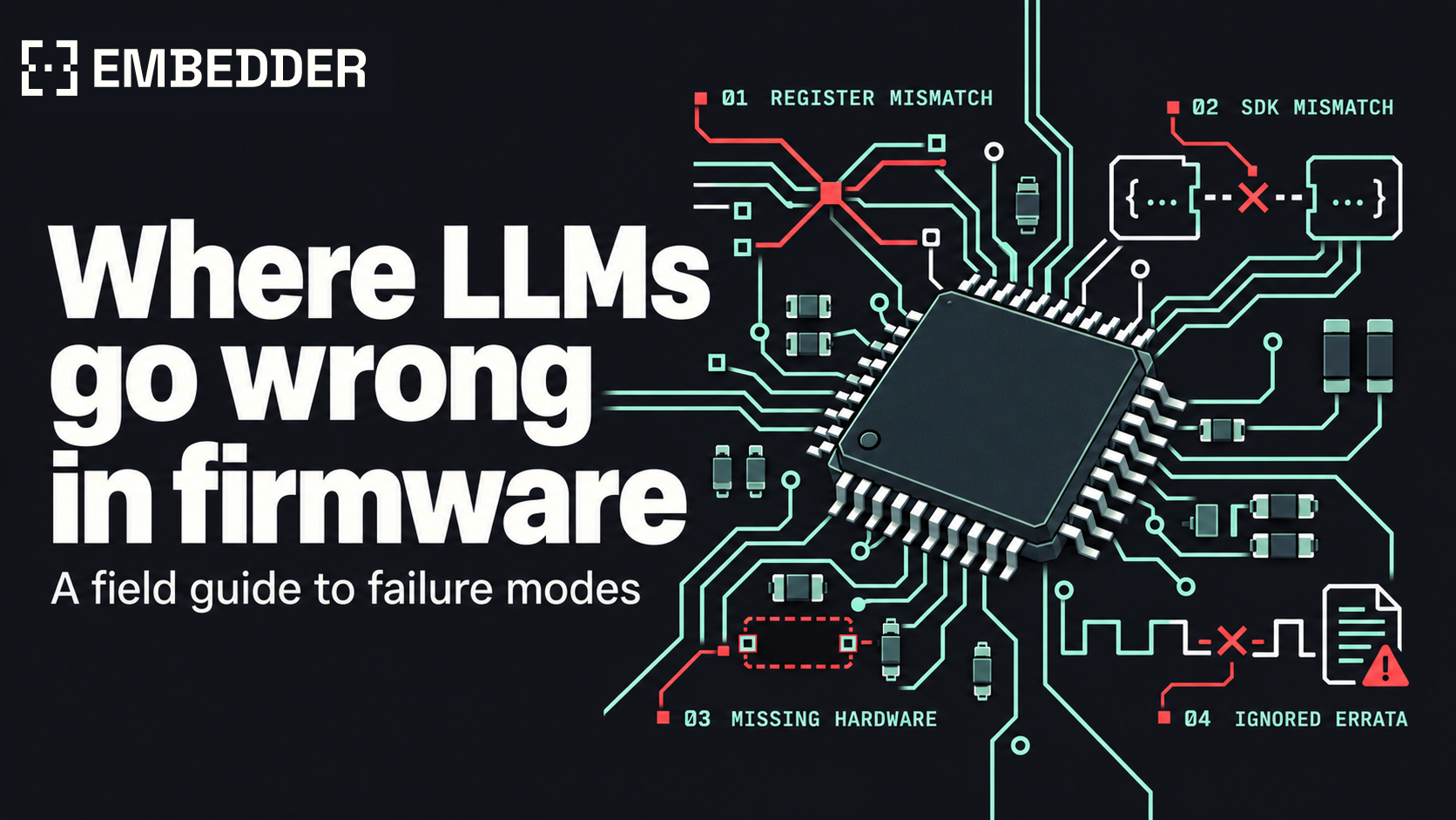
Invented register names, fabricated SDK calls, peripherals that aren't on the board, and ignored errata, each with a documented example.
The firmware builds with zero warnings and flashes without complaint. Then the board comes out of reset and stops at the first debug print. Halt the CPU and it is spinning in a tight loop, polling bit 7 of address 0x40004400 for a transmit-ready flag that will never be set.
This is what UART code written for an STM32F4 does on an STM32G0. Both parts put USART2 at the same base address. On the F4, offset 0x00 is the status register and bit 7 means the transmit register is empty. On the G0, offset 0x00 is control register 1, and bit 7 is an interrupt enable this code never set. A general-purpose model asked for a bare-metal G0 driver can produce the F4 layout with full confidence: that layout dates to the STM32F1 in 2007, and the one the G0 uses arrived with the STM32F0 in 2012.
A firmware failure mode, in this guide, is a repeatable way a large language model (LLM) writes code that reads as correct and is wrong for the exact part number, SDK release, board, or silicon revision it will run on. The four covered here are invented register names, fabricated SDK calls, peripherals that aren't on the board, and ignored errata. Each one comes from missing context, and the same models write correct firmware when they have it.
The underlying behavior has been measured outside firmware. A USENIX Security 2025 study generated 576,000 Python and JavaScript samples across 16 models and found that 19.7% of the packages those samples referenced did not exist, 205,474 unique invented names in total. An invented npm package fails at install, unless someone has already registered the name, which is the attack the study warns about. An invented register offset compiles, and the first sign of trouble is on the bench.
The four failure modes at a glance
Each failure mode traces back to a document the model did not have, and each is caught at a different stage.
| Failure mode | Example in this guide | Where it gets caught | Source that prevents it |
|---|---|---|---|
| Invented register names | STM32F4 USART layout on an STM32G0 | Compile time with vendor headers; on the bench with raw addresses | Reference manual or SVD file for the exact part |
| Fabricated SDK calls | gpio_pin_write() in a current Zephyr tree |
Compile or link time | Headers and docs of the pinned SDK release |
| Peripherals that aren't on the board | Clock setup that assumes a dev kit's crystal | First boot | Schematic and bill of materials |
| Ignored errata | Register access straight after a clock enable on an STM32F405/407 | On hardware, often only at higher optimization levels | Errata sheet for the silicon revision |
1. Invented register names
STM32 families reuse peripheral names and change the registers underneath them. On the F1 and F4, a USART has a status register (SR) and one data register (DR). On the F0, G0, L4, F7, and H7, status is read from ISR, flags are cleared through ICR, and data is split across RDR and TDR. The offsets changed along with the names.
| Offset | STM32F4 (RM0090) | STM32G0 (RM0444) |
|---|---|---|
0x00 |
SR |
CR1 |
0x04 |
DR |
CR2 |
0x08 |
BRR |
CR3 |
0x0C |
CR1 |
BRR |
0x1C |
no register | ISR |
0x28 |
no register | TDR |
A model that defaults to the F4 layout on a G0 target writes something like this:
/* Target: STM32G071, bare metal, no vendor headers.
   Written with the STM32F4 USART layout. Clock and pin setup omitted. */
#define USART2_BASE   0x40004400UL
#define USART2_SR     (*(volatile uint32_t *)(USART2_BASE + 0x00))  /* F4 layout */
#define USART2_DR     (*(volatile uint32_t *)(USART2_BASE + 0x04))  /* F4 layout */
#define USART2_BRR    (*(volatile uint32_t *)(USART2_BASE + 0x08))  /* F4 layout */
#define USART2_CR1    (*(volatile uint32_t *)(USART2_BASE + 0x0C))  /* F4 layout */

void uart_init(void)
{
    USART2_BRR = 0x0683;                    /* on a G0 this lands in CR3 */
    USART2_CR1 = (1UL << 13) | (1UL << 3);  /* UE | TE on an F4; on a G0 this lands in BRR */
}

void uart_putc(char c)
{
    while (!(USART2_SR & (1UL << 7))) { }   /* on a G0 this polls CR1 bit 7 (TXEIE) */
    USART2_DR = (uint8_t)c;                 /* on a G0 this lands in CR2 */
}
With ST's CMSIS device header, this mistake is cheap. USART2->DR and USART2->SR do not exist in the G0's USART_TypeDef, so the build fails on those lines. Written against raw addresses, as above, the code compiles for either family. On the G0 the init function puts the baud rate value in CR3 and the control word in BRR, the peripheral is never enabled, and uart_putc() waits on a bit that stays at zero.
The same driver written for the G0, per RM0444:
/* Target: STM32G071, bare metal, register layout per RM0444.
   Clock and pin setup omitted. */
#define USART2_BASE   0x40004400UL
#define USART2_CR1    (*(volatile uint32_t *)(USART2_BASE + 0x00))
#define USART2_BRR    (*(volatile uint32_t *)(USART2_BASE + 0x0C))
#define USART2_ISR    (*(volatile uint32_t *)(USART2_BASE + 0x1C))
#define USART2_TDR    (*(volatile uint32_t *)(USART2_BASE + 0x28))

void uart_init(void)
{
    USART2_BRR = 0x0683;                    /* 9600 baud from a 16 MHz kernel clock */
    USART2_CR1 = (1UL << 3) | (1UL << 0);   /* TE | UE */
}

void uart_putc(char c)
{
    while (!(USART2_ISR & (1UL << 7))) { }  /* TXE / TXFNF */
    USART2_TDR = (uint8_t)c;
}
The check is mechanical: every address, register name, and bit position compared against the SVD file or reference manual for the exact part number. Embedder runs it through register lookup for the selected MCU, and can read the live value from the target to confirm what the code wrote.
2. Fabricated SDK calls
A fabricated SDK call is a function that does not exist in the SDK release the project builds against. Some existed in an earlier release. Others were assembled from the library's naming conventions and never existed anywhere.
Zephyr has an example of the first kind. gpio_pin_write() and gpio_pin_read() were deprecated in Zephyr 2.2, released in March 2020, and removed in Zephyr 2.4. Tutorials written before then are still online, and a model can reproduce their style in a project pinned to Zephyr 4.x:
/* Zephyr 2.1-era GPIO style. Removed APIs; does not build on current Zephyr. */
#include <zephyr.h>
#include <device.h>
#include <drivers/gpio.h>

void main(void)
{
    struct device *dev = device_get_binding("GPIO_0");

    gpio_pin_configure(dev, 13, GPIO_DIR_OUT);
    gpio_pin_write(dev, 13, 1);
}
In a current tree the old include paths, GPIO_DIR_OUT, and gpio_pin_write() are all gone, and the build stops. The current API takes the pin from devicetree:
/* Devicetree-based GPIO for current Zephyr (4.x). */
#include <zephyr/kernel.h>
#include <zephyr/drivers/gpio.h>

static const struct gpio_dt_spec led = GPIO_DT_SPEC_GET(DT_ALIAS(led0), gpios);

int main(void)
{
    if (!gpio_is_ready_dt(&led)) {
        return 0;
    }

    gpio_pin_configure_dt(&led, GPIO_OUTPUT_ACTIVE);
    gpio_pin_set_dt(&led, 1);
    return 0;
}
The second kind follows a library's naming pattern. STM32Cube's HAL has HAL_GPIO_WritePin() and its LL layer has LL_GPIO_SetOutputPin(). HAL_GPIO_SetPin() reads like a member of the same family and is in neither.
Both kinds fail at compile or link time, before anything is flashed. A harder case is a call that exists in two SDKs with different meanings. xTaskCreate() takes its stack depth in words in upstream FreeRTOS and in bytes in ESP-IDF, so a value copied between them is off by a factor of four on a 32-bit MCU and still builds. Our FreeRTOS-to-Zephyr migration guide covers that case and several like it.
The defense is to pin the SDK release before any code is generated, then give the model that release's headers and documentation. Embedder's FreeRTOS-to-Zephyr migrations with engineering teams start the same way: the destination release is pinned first.
3. Peripherals that aren't on the board
This failure has two levels. At the part level, the peripheral exists in the product family and is missing from your part number. At the board level, the chip has it and the board does not connect it, or connects it differently from the vendor's development kit.
The part-level version is caught by the compiler. ESP32 code that drives the on-chip DAC will not build for an ESP32-C3: ESP-IDF's DAC driver supports the ESP32 and ESP32-S2, and the C3 has no DAC to drive.
The board-level version compiles. The clock setup below is correct for an STM32F4 Discovery board, which has an 8 MHz crystal on the HSE pins:
/* Clock setup that assumes an 8 MHz crystal on HSE.
   Correct for an STM32F4 Discovery; wrong for a board with a
   different crystal, an external clock, or nothing on HSE. */
RCC_OscInitTypeDef osc = {0};

osc.OscillatorType = RCC_OSCILLATORTYPE_HSE;
osc.HSEState       = RCC_HSE_ON;
osc.PLL.PLLState   = RCC_PLL_ON;
osc.PLL.PLLSource  = RCC_PLLSOURCE_HSE;
osc.PLL.PLLM       = 8;                 /* 8 MHz / 8 = 1 MHz PLL input */
osc.PLL.PLLN       = 336;               /* 336 MHz VCO */
osc.PLL.PLLP       = RCC_PLLP_DIV2;     /* 168 MHz PLL output */
osc.PLL.PLLQ       = 7;                 /* 48 MHz for USB */

if (HAL_RCC_OscConfig(&osc) != HAL_OK) {
    Error_Handler();                    /* no clock on HSE: execution stops here */
}
ST's STM32F4 Nucleo-64 boards ship with that crystal position unpopulated. Current revisions feed an 8 MHz clock from the on-board ST-LINK into the MCU's oscillator input instead, which firmware selects with HSE bypass mode, not RCC_HSE_ON. A custom board may have a 25 MHz crystal, or nothing on HSE at all. With no clock source on HSE, the oscillator never reports ready, HAL_RCC_OscConfig() times out after 100 ms, and the CubeMX-generated Error_Handler() is an infinite loop, so the board appears dead before it prints a character. With a 25 MHz crystal, the same divider values put the PLL input at 3.125 MHz, outside its specified 1 to 2 MHz range, and the VCO far above its 432 MHz limit.
Bus addresses work the same way. A Bosch BME280 answers at I2C address 0x76 or 0x77 depending on how its SDO pin is strapped, and the schematic is where that is recorded.
The source for all of this is the schematic and bill of materials for the board revision on the bench. Embedder reads the design files from Altium, KiCad, Eagle, PADS, or Xpedition and checks firmware against the board's components, pins, nets, and power connections, so a clock source or an address strap comes from your netlist. Inferred addresses and part matches still get an engineer's review before a hardware change, and the documentation says so.
4. Ignored errata
A reference manual describes the chip as designed. An errata sheet lists where shipped silicon behaves differently, revision by revision. For the STM32F405/407 and F415/417, that document is ES0182, 45 pages at Rev 19 (July 2026).
Section 2.2.13 of ES0182, "Delay after an RCC peripheral clock enabling," says a peripheral's registers may not respond for a short time after its clock-enable bit is set: up to two AHB clock cycles for a peripheral on AHB, and up to 1 + the AHB/APB prescaler for a peripheral on APB. On an STM32F407 running at 168 MHz with APB1 at 42 MHz, a prescaler of 4, that is up to five cycles for USART2. This code follows the reference manual and skips the wait:
/* STM32F407 at 168 MHz, APB1 at 42 MHz (AHB/APB1 prescaler 4).
   Follows RM0090, ignores ES0182 section 2.2.13. */
RCC->APB1ENR |= RCC_APB1ENR_USART2EN;
USART2->BRR = 0x016D;                       /* 115200 baud from 42 MHz */
USART2->CR1 = USART_CR1_UE | USART_CR1_TE;
Compiled with GCC 12 through 14 at -O0, -O1, or -Os, a literal-pool load and a constant load sit between the clock-enable store and the BRR write. Two instructions is less than the five-NOP workaround the erratum gives for this prescaler, so that gap is slack, not a guarantee. At -O2 the compiler schedules the BRR store as the very next instruction after the clock enable, with no margin at all against the window the erratum describes. A dropped write leaves BRR at its reset value of zero, so the USART comes up enabled with no baud rate and nothing readable reaches the terminal. The same source can work at -O0 and fail at -O2, with no change to the driver.
/* STM32F407: with the ES0182 section 2.2.13 workaround. */
RCC->APB1ENR |= RCC_APB1ENR_USART2EN;
(void)RCC->APB1ENR;                         /* dummy read-back covers the enable delay */
USART2->BRR = 0x016D;
USART2->CR1 = USART_CR1_UE | USART_CR1_TE;
The erratum also allows a DSB instruction or a fixed number of NOPs in place of the read-back. ST's HAL already applies the read-back: its clock-enable macros read the enable register after setting the bit, under a comment with the erratum's title. A request for register-level code "without the HAL" drops the workaround along with the abstraction, unless the errata sheet is part of what the model reads.
The check here is the errata sheet for the silicon revision on the bill of materials, read against every peripheral the firmware uses. Embedder indexes errata alongside reference manuals, datasheets, and SVD files, and cites the section behind each hardware-specific value it writes.
The common cause: a document the model didn't have
Each failure is a missing fact, and each fact is written down somewhere outside the source tree: the reference manual for the exact part, the headers of the pinned SDK release, the schematic for the board revision, the errata sheet for the silicon revision. A model working from training data alone fills those gaps with the pattern it has seen most often, which tends to be an older part or a vendor's development kit.
The first control is to put the documents in front of the model and require a citation for every hardware-specific value. The second is to run the result on the target and keep the evidence, because code like the errata example reads correctly and fails on silicon.
A careful firmware engineer already makes these checks in review. Model-written drafts raise the volume of code that needs them. As a checklist:
- Compare every register name, offset, and bit position with the SVD file or reference manual for the exact part number.
- Pin the SDK release and resolve every API call against that release's headers.
- Check pins, clock sources, bus addresses, and pull-ups against the schematic for the board revision.
- Read the errata sheet for the silicon revision against every peripheral in use.
- Build, flash, and observe on the target, and save the serial output, register dumps, and captures with the change.
Same models, better context
The models behind the four failures above are also the reason AI-written firmware is possible at all. An LLM with a domain-specific harness can read a reference manual of more than a thousand pages, follow a clock tree across chapters, write a driver in the project's own style, interpret a build log, and propose the next fix. Code generators and templates before them covered a small part of that range.
What a general-purpose model lacks is your project. It was trained to be good at everything from web apps to contracts, so it has no way to know which part number is on your board, which SDK release your tree is pinned to, or which silicon revision is on the bill of materials. Asked anyway, it answers with the most common pattern it has seen, and the four failures follow.
How Embedder checks code against the part, the board, and the silicon
Embedder is the layer that supplies both: the facts about your hardware and a way to test against it. It is an AI platform for firmware that runs on general-purpose models and gives them the datasheet, reference manual, SVD file, schematic, and errata for the exact part. It checks register values, bit fields, timing constants, and pin assignments against those sources, cites the source behind each hardware-specific decision, and flags values it cannot support for review.
Specialized agents share the work, and an orchestrator chains the build, flash, and test steps on the board through the compiler, debugger, probes, and instruments the team already uses, so the model sees what the chip did. Serial traces and register dumps are attached to its conclusions. The model does the reading, reasoning, and writing. Embedder supplies the facts and checks the result on hardware.
A general-purpose assistant can reach the same result if your team supplies the documents and builds the bench automation around it. Embedder packages that work for teams shipping production firmware: a catalog of hundreds of platforms and thousands of peripherals with their documentation, schematic ingestion, and hardware-in-the-loop testing in one workflow. Teams connect the model provider they choose, including local models, so each stronger model gets the same documents and the same bench loop.
Tell us where this breaks
This guide covers four failure modes with one main example each, and firmware has more. If a model-written driver passed your review and failed on your bench, send us the part number, the SDK release, and the symptom. If one of the examples above is wrong for a silicon revision or SDK release we didn't consider, we want that too. Errata sheets get revised, and this guide will be as well.
FAQ
What is an LLM failure mode in firmware?
It is a repeatable way a language model writes firmware that reads as correct and is wrong for the exact part number, SDK release, board, or silicon revision. The four covered here are invented register names, fabricated SDK calls, peripherals that aren't on the board, and ignored errata.
Why do LLMs get register names wrong?
Vendors reuse peripheral names across families while changing register names and offsets. STM32F4 USARTs use SR and DR. STM32G0 USARTs use ISR, RDR, and TDR at different offsets. Without the reference manual or SVD file for the exact part, a model falls back on the layout with the longest public history.
Does the compiler catch hallucinated firmware code?
Sometimes. Vendor headers turn a wrong register name or a removed SDK call into a build error. Raw addresses, board-level assumptions such as a missing crystal, and skipped errata workarounds all compile and then fail on hardware.
What is an errata sheet, and why does it affect AI-written firmware?
An errata sheet lists the ways shipped silicon differs from its reference manual, by revision. ST's ES0182 for the STM32F405/407 requires a delay after enabling a peripheral clock, and code written from the reference manual alone leaves it out.
Can a general-purpose AI model write production firmware?
It can contribute drafts when it is given the reference manual, SDK headers, schematic, and errata for the target, and when every change is verified on hardware. Without those inputs, the four failure modes in this guide are likely.
How does Embedder reduce these failures?
Embedder indexes manuals, datasheets, errata, and SVD files, reads schematics from Altium, KiCad, Eagle, PADS, and Xpedition, cites the source for each hardware-specific value, and runs build, flash, and test loops on the target board.
Is the LLM the problem?
No. The model is the part that reads the manual, reasons about the design, and writes the code. What a general-purpose model lacks is the project's part number, SDK release, schematic, and errata. Embedder supplies those, orchestrates the agents doing the work, and verifies the output on hardware.